The arm arrives and makes its first moves
The Hiwonder LeArm AI arrived and moved under PC control for the first time, and a 4K camera joined the setup. Each joint stops 1-2.5 degrees short of its target, which shapes how the arm will tap a phone screen.
 Open the photo large
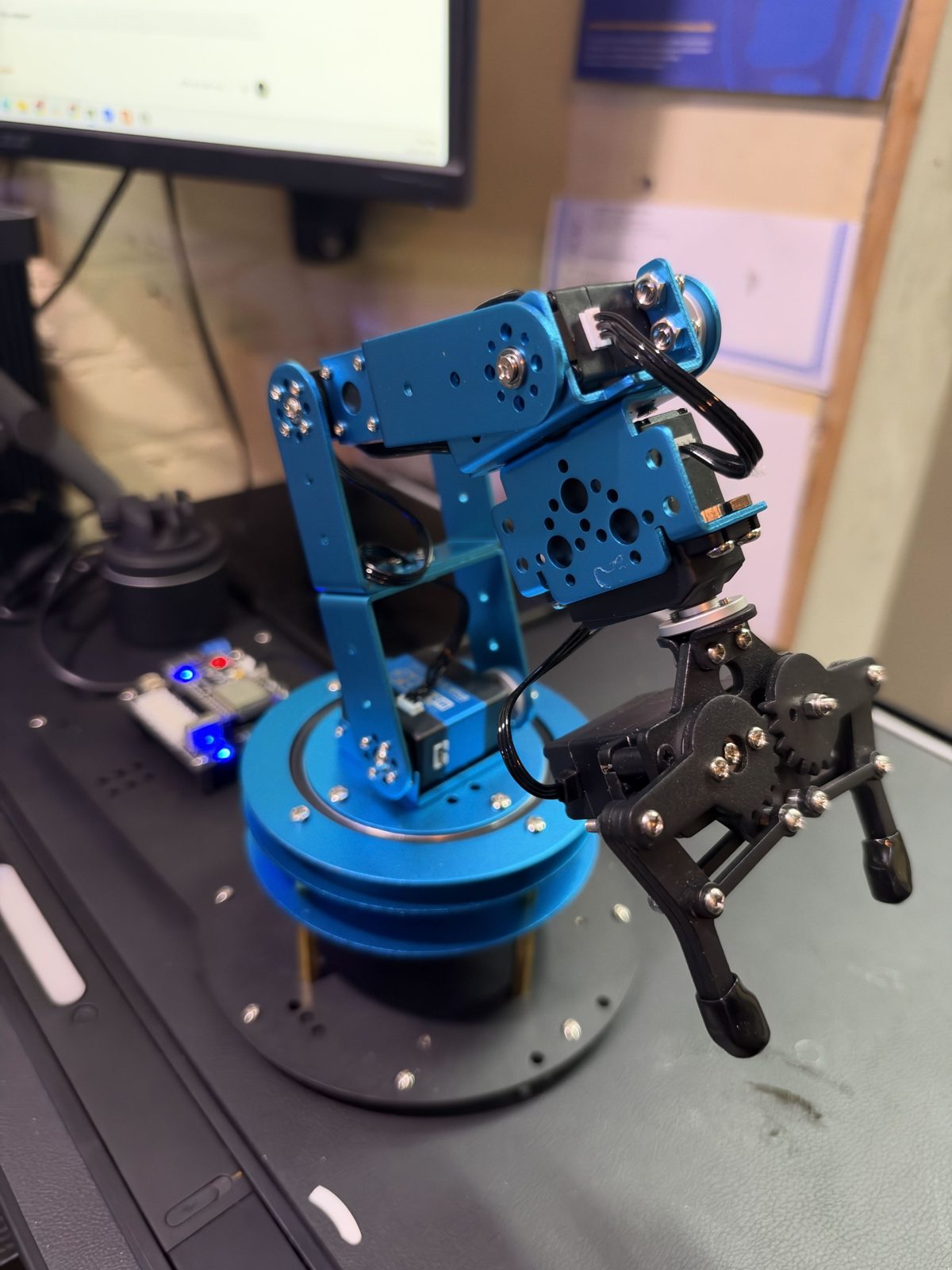
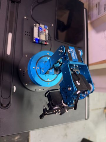
The assembled Hiwonder LeArm AI with its ESP32 controller powered on: six bus servos that report their own positions to the PC.
Photo: Ravi (iPhone)
What we did
- Connected the Hiwonder LeArm AI to the PC over USB and wrote our own Python driver (
arm/learm.py) that reads all six joints and can move any of them; the first test turned the wrist about 10 degrees and back. - Ran a demo routine (
tools/arm_demo.py) that turns the base, lifts and lowers the arm and twists the wrist. After a slow first run we made each move three times faster and added the gripper; the next two runs took 12.6 s and 13.4 s. - Checked every move against the servos' own readings: each joint stopped 1-2.5 degrees short of its target, always on the side it came from.
- Ravi watched the runs and confirmed which way the arm moves: higher base numbers turn it to the right as seen facing it, moving the elbow and wrist toward 500 (straight up) lifts it, and higher gripper numbers close the gripper.
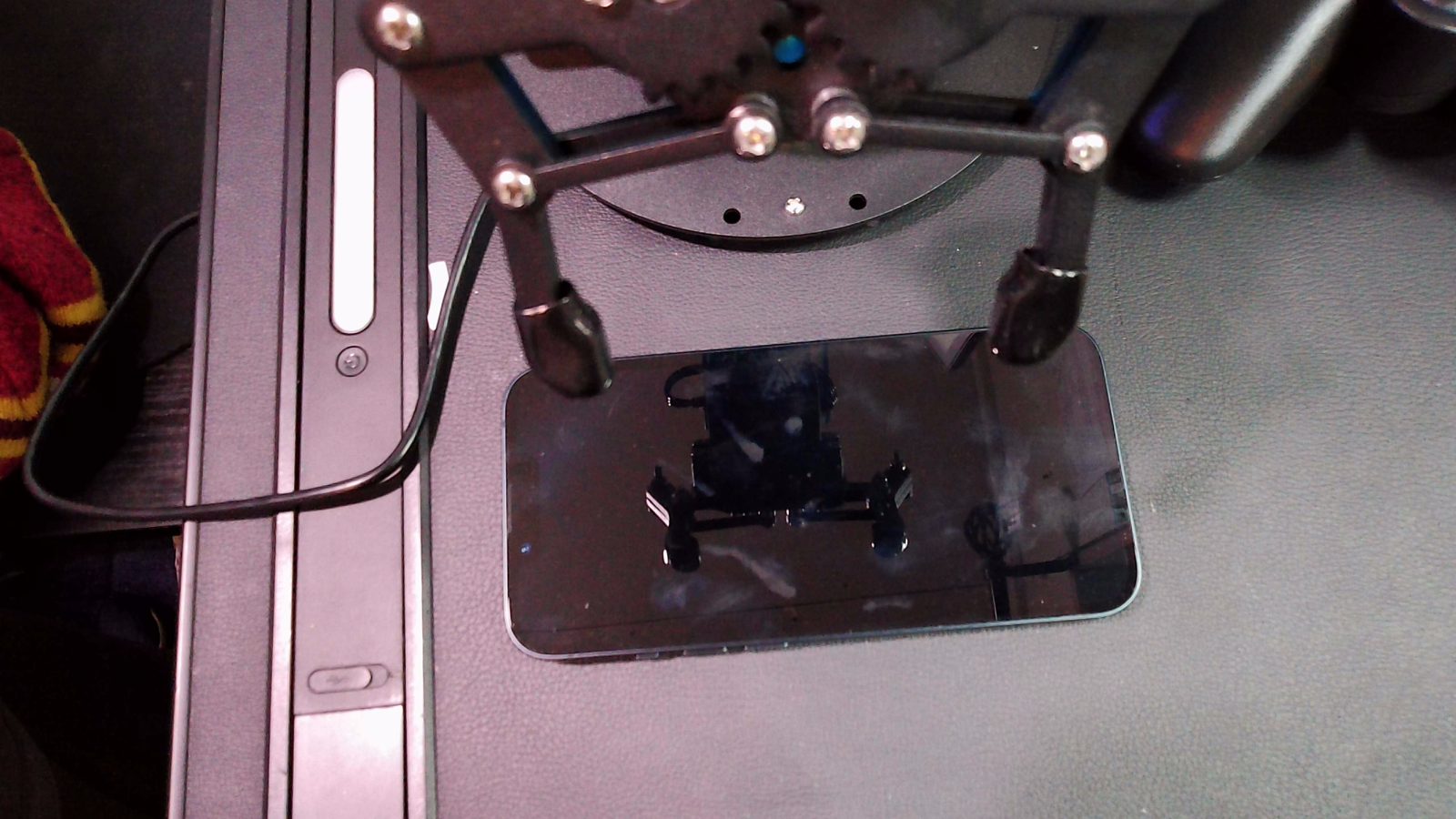
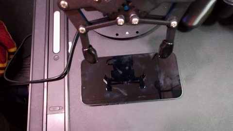
- Ravi connected an EMEET SmartCam C980 Pro 4K and we made it the main camera: a steady 30.0 fps at 1080p with no dropped frames, and a first 4K view looking down at the gripper over the phone.
- Read Hiwonder's factory firmware source for the arm's link lengths (2.89, 10.43, 8.9 and 17.7 cm), the target limits it enforces and its power-up move, and kept a copy in the project.
- Planned the phone rig step by step: a stylus grounding check, a base board, a camera mast and an emergency stop, then joint limits, a reach map and repeatability tests.
What we learned
- Bus servos
- A bus servo is a small networked motor: all six share one serial wire, each has an ID, and each reports its measured position. That feedback let us check every move from the motors' own readings before any camera was connected.
- Deadband
- A servo stops once it is close enough to its target; that window is its deadband. It is why our joints land short on the side they came from, and why corrections under about 2 degrees did nothing. At the base, 1.5 degrees moves a tip 20 cm out by about 5 mm, so precise taps need a same-side approach or a camera check.
- Serial protocol
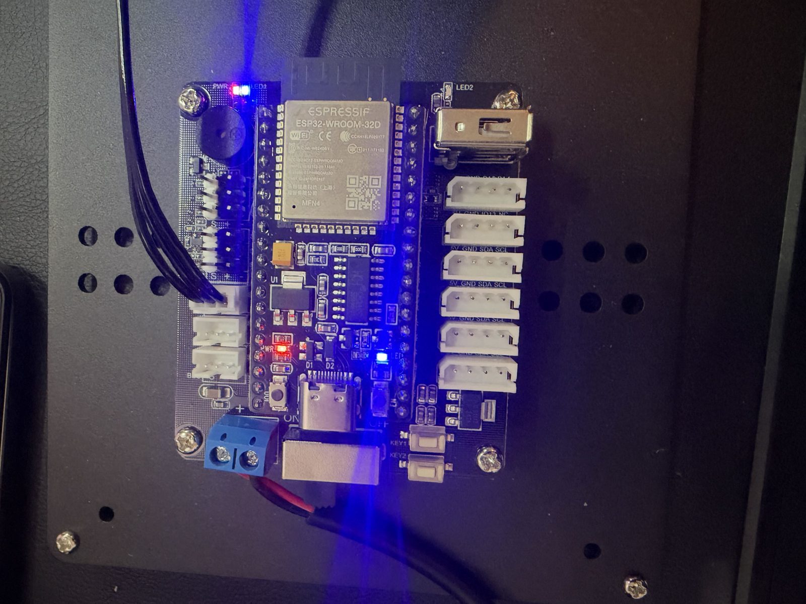
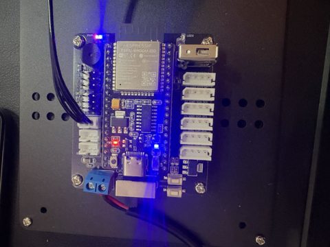
- The arm's USB-C port is a CH340 USB-to-serial chip, so the PC sees a plain serial port. Each command is a short byte frame (55 55, length, command, parameters) sent at 9600 baud. We sent read-only commands, firmware version and joint positions, before any move.
- Checking sensor readings
- Code that sends a sensor reading back as a command must check it first. A failed servo read reaches the PC as 63488, far outside the 0-1000 range; sent back as a target, it could swing a joint about 90 degrees fast. Our driver now rejects such readings and refuses out-of-range targets instead of clamping them.
- Capacitive touch
- A phone screen registers a touch when a conductor coupled to ground lands on the glass. A hand supplies that coupling, but a stylus held in an insulated gripper has almost none, so it may need a thin ground wire. A 5-minute bench test will show whether ours does.
Numbers
| Joints | 6 bus servos |
|---|---|
| Position step | 0.24 deg per unit (0-1000 = 0-240 deg) |
| Serial link | 9600 baud |
| Fast demo run time | 12.6 s and 13.4 s |
| Joint shortfall (deadband) | 1-2.5 deg (3-11 units) |
| Firmware target limits | 125-875 units (gripper 200-700) |
| Power-up move to rest | 1 s; tip about 14.5 cm ahead, 1.6 cm up |
| Camera at 1080p | 30.0 fps, 0 dropped frames |
Problems and fixes
A USB dongle from the kit, plugged into the PC, looked like a Bluetooth adapter.
Fix: It is the receiver for the kit's wireless gamepad and belongs in the arm controller's receiver port; the PC does not need it.
Small errors added up from run to run: the base drifted from 503 to 497 to 492, because each demo started where the last one ended.
Fix: The demo now moves relative to a fixed rest pose, and the next run ended at 495.
A failed servo read arrives as 63488; sent back as a target, it could have swung a joint about 90 degrees fast.
Fix: The driver now rejects readings outside 0-1000 and refuses out-of-range targets; a read-back afterwards showed every joint reading normally.
Every power-up swings the arm to its rest pose in 1 s, and the tip lands about where the phone lies.
Fix: Not fixed yet: once a stylus is mounted, take the phone out before switching on, and later place the phone off to one side of that path.
In the first 4K view the phone's screen was off, showing only reflections, and the gripper looked close to the camera.
Fix: Not fixed yet: wake the phone with auto-lock off, and raise the camera a few inches so the arm cannot hit it.
Next
- Order parts and build the rig: a base board clamped to the table, the phone flat and off the power-up path, the camera on a rigid mast at least 20 cm from the screen, and an emergency stop in the power lead.
- Run a 5-minute stylus check: does a touch register on the screen with and without a ground wire?
- With Ravi watching, find each joint's real limits in small steps, write our own arm maths in Python, and map the reach over the screen's corners and centre.
- Then measure repeatability (one spot tapped 20 times) and test swipes on a test page.
Photos and videos
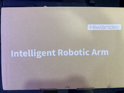 Open the photo large
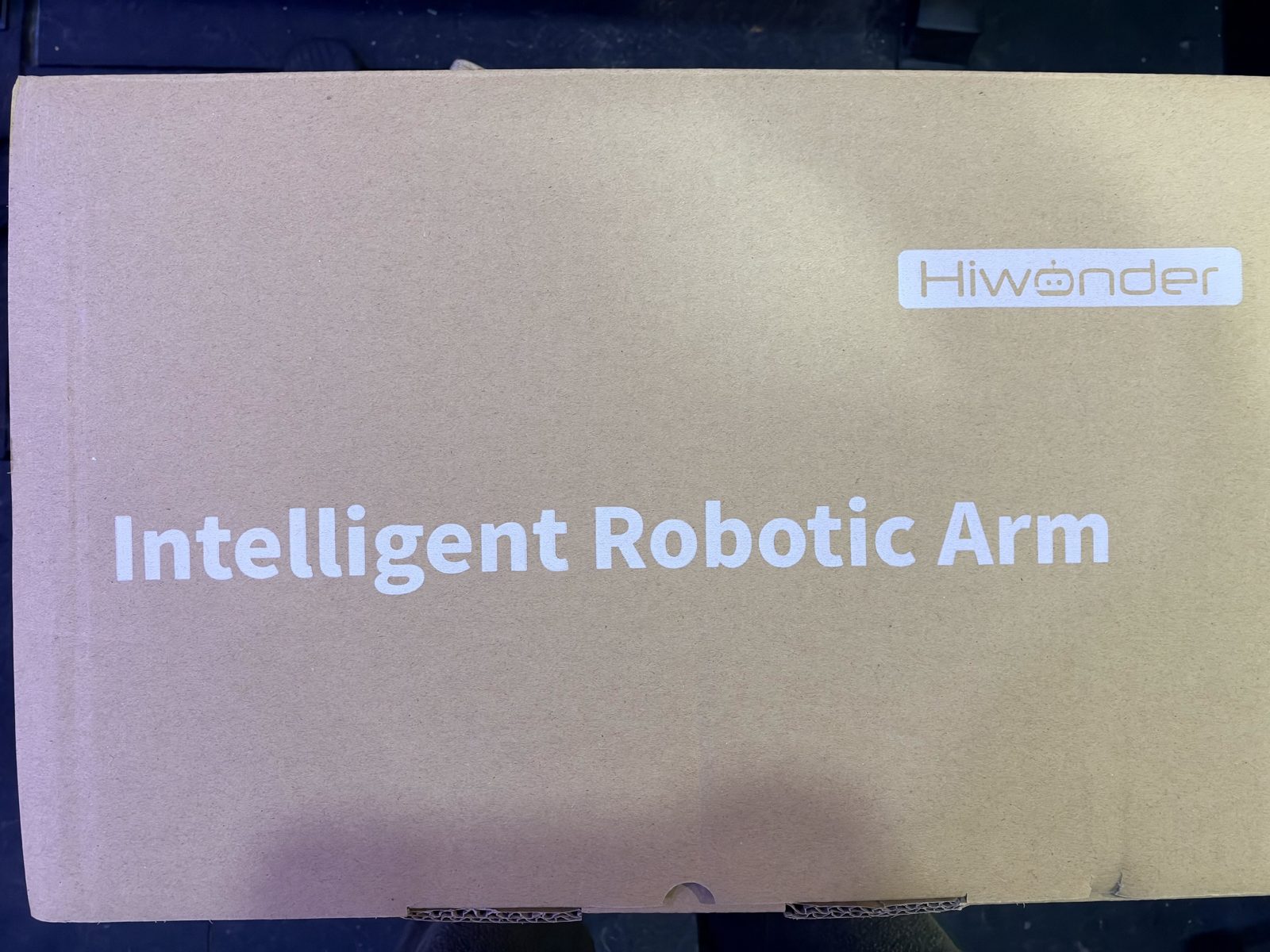
The arm's box as it arrived, printed with Hiwonder's name and Intelligent Robotic Arm.
Photo: Ravi (iPhone)
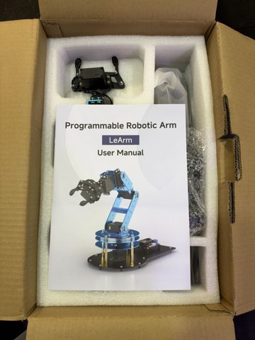 Open the photo large
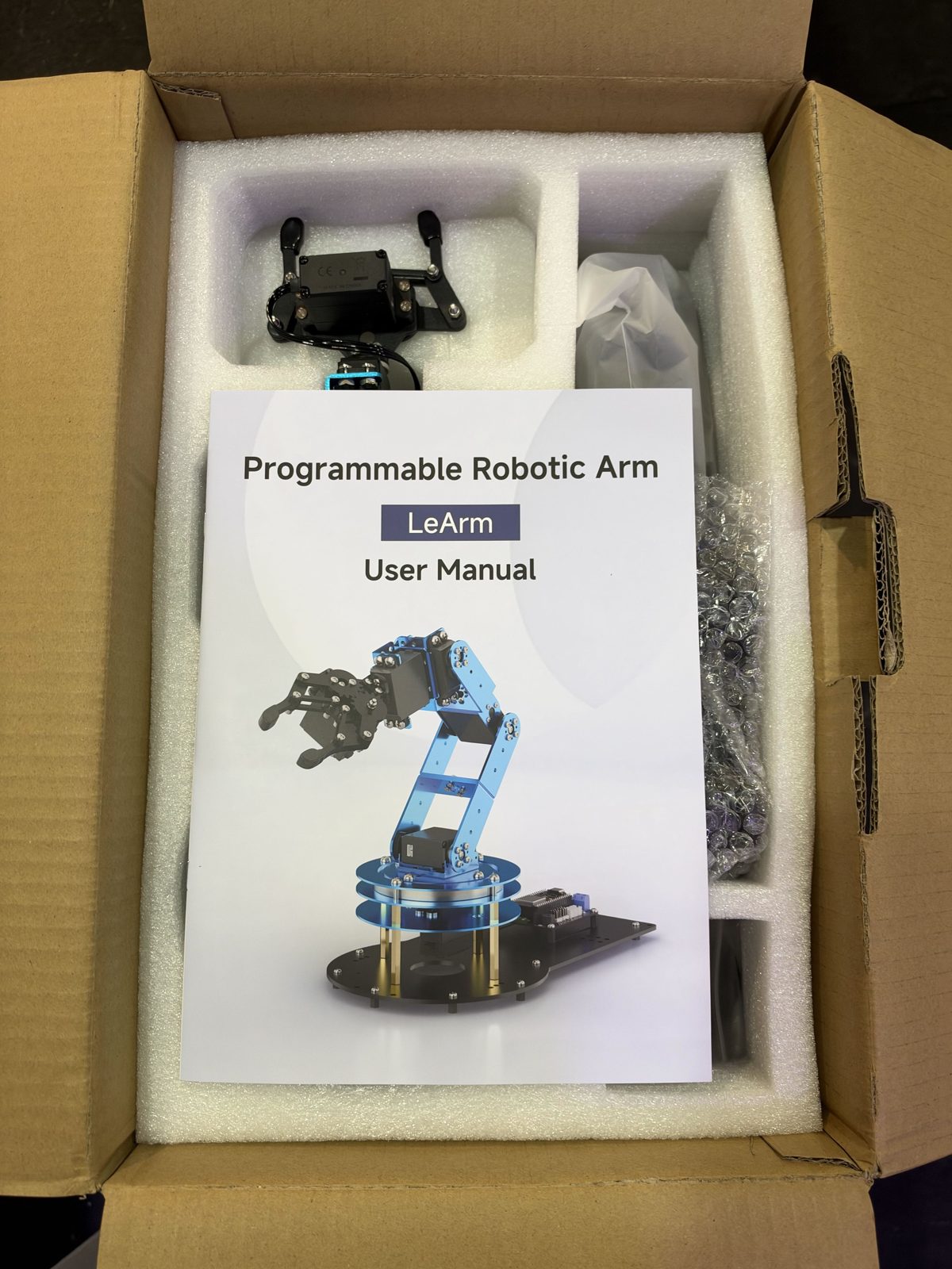
The opened box with the LeArm user manual on top; for PC control we worked from Hiwonder's online docs and protocol guide.
Photo: Ravi (iPhone)
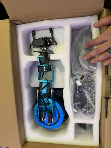 Open the photo large
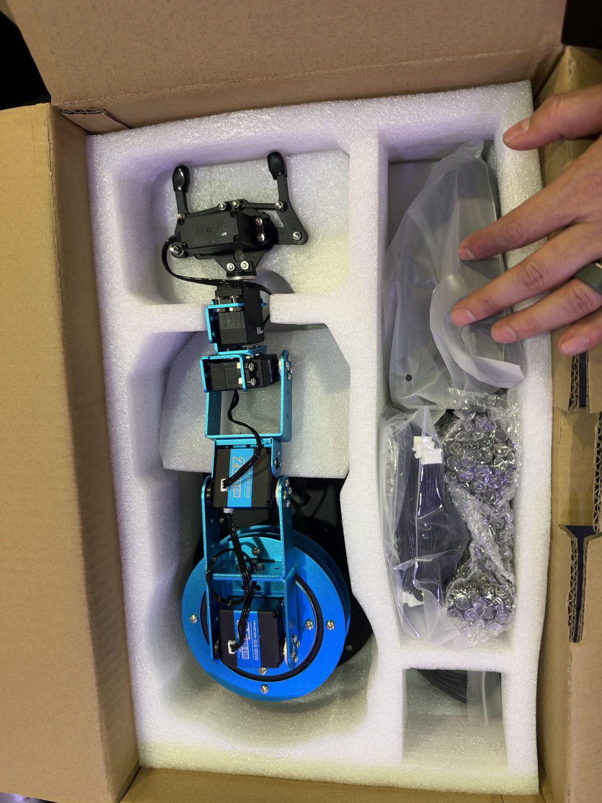
Unboxing: the arm arrives in foam already built, next to bags of cables and accessories.
Photo: Ravi (iPhone)
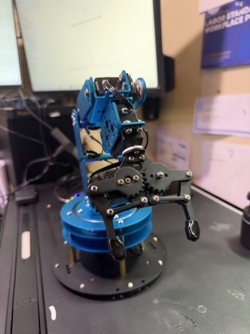 Open the photo large
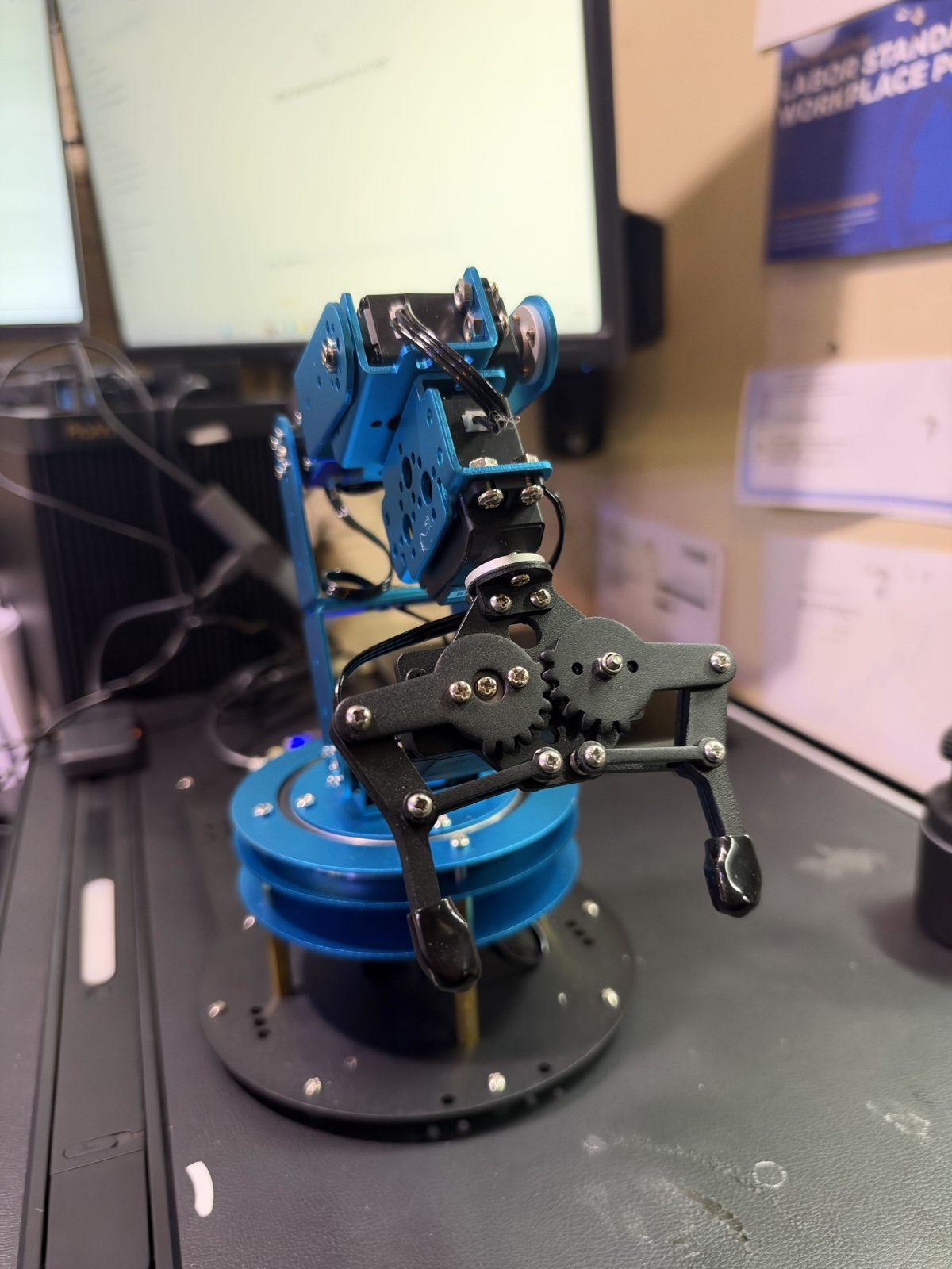
Close-up of the gripper: two geared fingers driven by one servo, where low numbers open it and high numbers close it.
Photo: Ravi (iPhone)
 Open the photo large
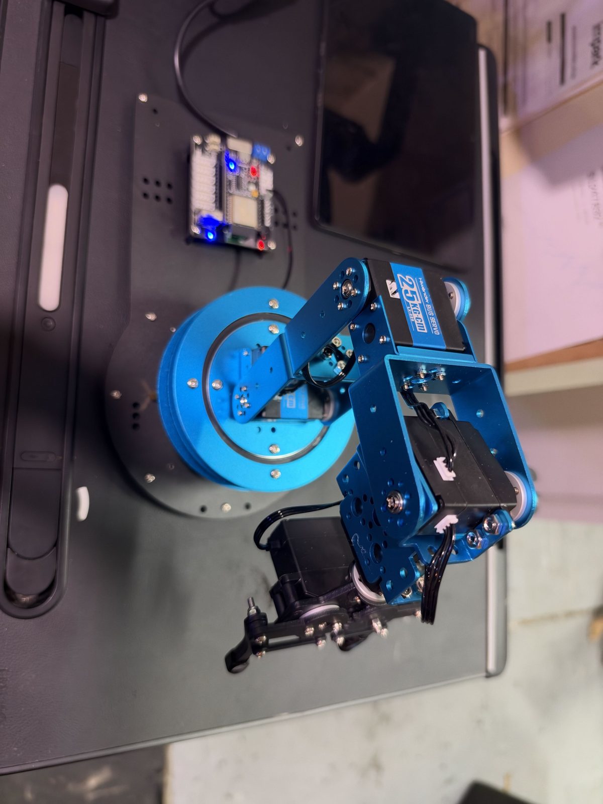
The arm on the desk from above, with the ESP32 controller lit beside the base: the board the PC talks to over USB-C.
Photo: Ravi (iPhone)
 Open the photo large
The ESP32 controller board up close: its USB-C port is a CH340 USB-to-serial link, which is how the PC sends commands and reads every joint.
Photo: Ravi (iPhone)
 Open the photo large
The first view from the new EMEET 4K camera: the gripper hangs over a phone lying flat, its screen still off and showing only reflections.
Photo: Robot camera (EMEET 4K)